All about CAN bus: why is it needed, how to read it, can it break
CAN bus is a semi-virtual concept. And yet, it is this exchange protocol that underlies all vehicle control.
What is CAN bus
CAN bus is a technology for exchanging data between electronic units and executive devices of a car. CAN stands for controller area network. Or, to put it simply, it is a protocol for exchanging signals over a common data bus, in which each information packet has its own address and is intended for only one control unit or device.
The standard was developed by the German company Bosch and presented in 1986. It is being improved and developed to this day.
Today, even the simplest cars are equipped with the CAN protocol, which simplifies diagnostics, increases fault tolerance, and makes wiring simpler. Sometimes in the context of auto topics, the abbreviation is interpreted as car area network – “local car network”.
How does CAN bus work?
In short, the main essence of the CAN protocol is the transmission of a signal from the control unit to the mechanism (and back) over a common network. And so that the command is not mistakenly received by a “foreign” performer, each information packet has its own identifier – just as each letter in a common mailbox has a unique addressee.
Thus, the signal sent by one of the network elements is “heard” by all participants, but only one of them accepts it for execution, recognizing its address encrypted in the signal. Unlike outdated information exchange systems, the CAN bus has a number of key differences and advantages.
- Significant reduction in the number of wires. If a modern car, especially an expensive and complex one, had classic wiring without CAN, its weight would increase by several tens of kilograms.
- Simplifying diagnostics. Simply connect the scanner to a single OBD connector, and all network components become available for testing or programming.
- High data transfer rate. Which is vital for modern control units and mechanisms.
- Noise immunity. An important point given today’s abundance of sources of interference and interference.
What does a CAN bus look like?

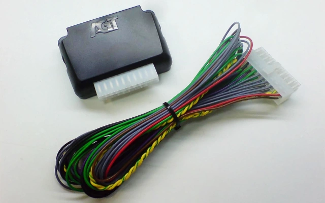
The general principle of CAN operation was described above, and if we consider the physical implementation, then the elements of CAN wiring are made as a twisted pair. This is a laying of wires in insulation, in which they are braided like a pigtail. First of all, this increases noise immunity. And the braided wire itself in common insulation is stronger than the classic parallel laying of wires.
Where is the CAN bus located?
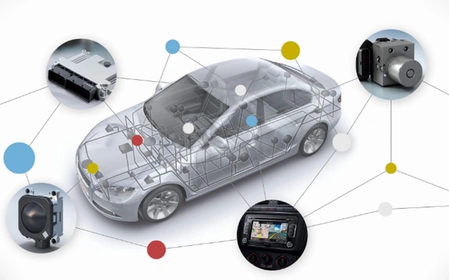
In short, everywhere. As discussed above, the CAN bus is not a single unit, wire, or device. The Internet can be used as an analogy. The CAN definition also includes many components united by a universal “communication” format.
In a modern car, almost all components with electrical wiring are connected by a CAN bus: from the engine control unit to the brake light LED. So, if the latter fails, the driver will see a warning on the instrument panel – the break will be registered by the lighting control unit, connected to the rear light via CAN.

Types of CAN buses
Today, the CAN protocol continues to develop, increasing the speed and efficiency of information exchange. There are two main types:
- Classic car CAN bus. Exchange is carried out at a speed of up to 1 Mbit/sec.
- CAN FD-bus. The data packet length has been increased from 8 to 64 bytes, and the maximum operating speed has been increased to 8 Mbit/sec.
Alternatives to CAN
Today, more advanced analogs of the CAN protocol are being actively developed (and are already being used). For example, the MOST bus uses optical fiber instead of copper wire. This solution further increases the performance of the automotive network – up to 21 Mbit/sec.
How to check CAN bus
There are several methods used to diagnose the car network. The most obvious is to inspect the wiring for mechanical damage. But it is often impossible to view the wiring along its entire length, so faults are looked for pointwise.
- Checking with a multimeter. The presence of voltage in the twisted pair is verified, as well as the nominal resistance values.
- Oscilloscope testing. A more complex and professional method that requires advanced auto electrician skills. The passage and correctness of control signals are examined.
- Checking with an OBD scanner. In some cases, computer diagnostics can indicate a malfunction of the tire components.


